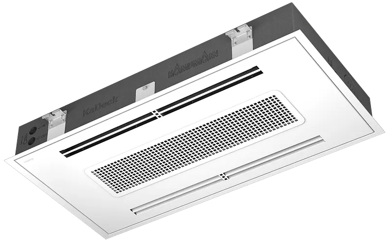
• United Kingdom English (United Kingdom)
  • Projects

Country and language

  • Germany

    Deutsch
  • France

    Français
  • Netherlands

    Nederlands
  • Switzerland

    DeutschFrançais
  • Austria

    Deutsch
  • Poland

    Polski
  • United Kingdom

    English (United Kingdom)
  • Canada

    English (Canada)Français (Canada)
  • Italy

    Italiano
  • USA

    English (United States)
  • Global

    EnglishРусский
  • Products
  • Tools
  • Service
  • Company
  • Magazine
  • Contact
        • ProductsArrow Right 1 Streamline Icon: https://streamlinehq.com
          • Trench TechnologyArrow Right 1 Streamline Icon: https://streamlinehq.com
            • Katherm HK
            • Katherm QK
            • Katherm QK nano
            • Katherm NK
            • Katherm QL
            • Katherm QE
          • Unit HeatersArrow Right 1 Streamline Icon: https://streamlinehq.com
            • TIP
            • TOP
            • Ultra
            • Ultra Allround
            • TOP C
          • Fan CoilsArrow Right 1 Streamline Icon: https://streamlinehq.com
            • Venkon
            • KaCool D AF
            • KaDius
            • KaDeck
            • PowerKon LT
            • Venkon XL
            • KaCool W
            • KaCool D HY
          • Heat pump radiatorsArrow Right 1 Streamline Icon: https://streamlinehq.com
            • Powerkon LT
          • Perimeter Heating
          • Decentralised Ventilation UnitsArrow Right 1 Streamline Icon: https://streamlinehq.com
            • WZA
          • Air curtainsArrow Right 1 Streamline Icon: https://streamlinehq.com
            • UniLine
            • Cassette UniLine
            • Tandem
            • Tandem - Cassette Version
            • ProtecTor
          • Design GrillesArrow Right 1 Streamline Icon: https://streamlinehq.com
            • Optiline
            • Wooden grilles
        • ToolsArrow Right 1 Streamline Icon: https://streamlinehq.com
          • Download Center
          • Calculation programs
        • ServiceArrow Right 1 Streamline Icon: https://streamlinehq.com
          • Customer Service
          • Project SupportArrow Right 1 Streamline Icon: https://streamlinehq.com
            • Site Survey and Installation
          • SeminarsArrow Right 1 Streamline Icon: https://streamlinehq.com
            • CPD Inhouse Seminars
            • CPD Webinars
        • CompanyArrow Right 1 Streamline Icon: https://streamlinehq.com
          • The Kampmann UK Ltd.
          • Research and development
          • Sustainability
          • Compliance
        • MagazineArrow Right 1 Streamline Icon: https://streamlinehq.com
          • News
          • Technology and knowledge
        • ContactArrow Right 1 Streamline Icon: https://streamlinehq.com
          • Find Contact
          • Contact Form
        • Home
        • Products
        • Fan coils
        • KaDeck
        • Calculation

        Products

        • Trench Technology
        • Unit Heaters
        • Fan Coils
        • Heat pump radiators
        • Air curtains
        • Perimeter Heating
        • Decentralised Ventilation Units
        • Design Grilles

        Company

        • The Kampmann UK Ltd.
        • Research and Development
        • Sustainablility
        • Magazine

        Support

        • Project Support
        • Customer Service
        • Contact
        • Seminars

        Contact

        +44 1932 228592info@kampmann.co.uk
        • Imprint
        • General Terms and Conditions
        • Central Data Protection Instructions
        • Cookies
        • Reporting system
        • Modern Slavery Statement
        • Compliance

        Our products are intended exclusively for B2B sales.

        KaDeck

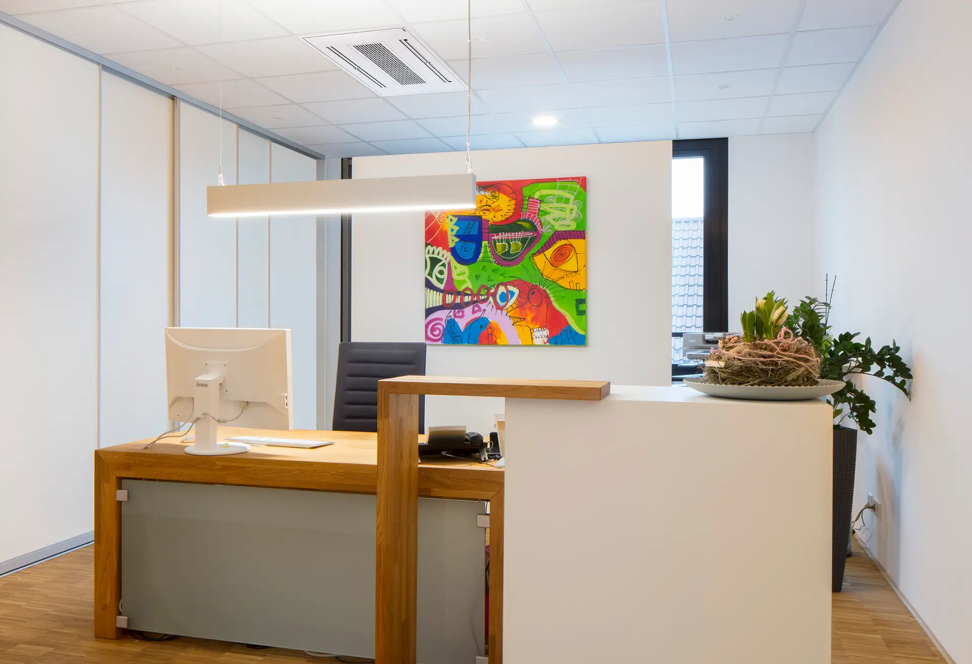
        Versatile air conditioning for existing and new-build offices.

        • Heating
        • Cooling
        • Ventilation
        Product image
        Exploded view
        Hero image
        • Overview
        • Variants
        • Calculation & selection
        • Planning information
        • Videos
        • Downloads

        Space-saving heating and cooling

        • For use with low suspended ceilings with an appliance height of 165 mm
        • Particularly light thanks to the EPP housing (expanded polypropylene)
        • No service hatches necessary: all relevant maintenance components are located in the unit
        • fulfills the requirements of VDI 6022

        Sheet steel and EPP hybrid housing

        • Rigidity and strength thanks to galvanized sheet steel frame
        • Thermal and acoustic isolation thanks to thermal bridge-free foamed EPP body
        • Organic interior shapes for easy cleaning

        Connection frame and ceiling panel

        • Optionally suitable for 600x600 mm or 625x625 mm ceiling grid
        • Ceiling panel and frame in RAL 9016 (traffic white), color selection according to customer requirements possible
        • Ceiling panel can be opened without tools, hinges and locks in industrial quality for an extremely long service life
        • Internal cleanable ISO Coarse air filter for dust protection of the internal components

        ease of installation and maintenance

        • Ceiling panel and condensate tray can be opened without tools
        • No service hatches required on site
        • All components can be reached after removing the condensate tray
        • Easy cleaning of all air-conducting surfaces possible
        • Valve installation (adjustable 2-way or differential pressure independent) inside the housing

        connection and operational safety

        • Device design and component selection optimized for easy installation and operation
        • Reduction of the total weight of the device to 60% compared to a sheet steel construction for back-friendly installation on the ceiling
        • Connection areas in the EPP with flow and return, primary air labeled

        Heat exchanger

        • High-efficiency heat exchanger with copper tubes and aluminum fins
        • Suitable for LPHW heating systems

        Condensate tray

        • Condensate tray can be removed without tools for cleaning and maintenance
        • for thermal and acoustic isolation consisting of EPP
        • Condensate-bearing area made of ABS plastic, suitable for disinfectants
        • Gradient on all sides for fast and complete condensate removal from the air-bearing area

        durable EC tangential fan

        • Noise-optimized, quiet-running 3-speed, stepless and energy-saving EC motor
        • Horizontal cross-flow roller, aerodynamically optimized EPP/aluminium contour in CFD
        • Patent-protected bypass motor cooling against heat build-up in heating mode to increase motor service life by 40%

        Primary air supply

        • Two spigots can each be connected at the head end
        • Easy removal of the EPP closures
        • Primary air is routed via the heat exchanger for temperature control

        System

        2-pipe system

        With this design, the entire heat exchanger surface is available for temperature control, depending on the medium currently present in the pipe system (cold or hot water). Switch-over between heating and cooling takes place centrally via the building management system. This variant is particularly suitable for applications with seasonal switch-over and reduced installation effort.

        4-pipe system

        This version is suitable for sophisticated air conditioning concepts in which each room zone or unit can be switched over individually between heating and cooling. By routing the heating and cooling medium separately, the system offers maximum flexibility and comfort - ideal for buildings with changing usage requirements.

        Type of system
        2-pipe
        4-pipe

        Unit design

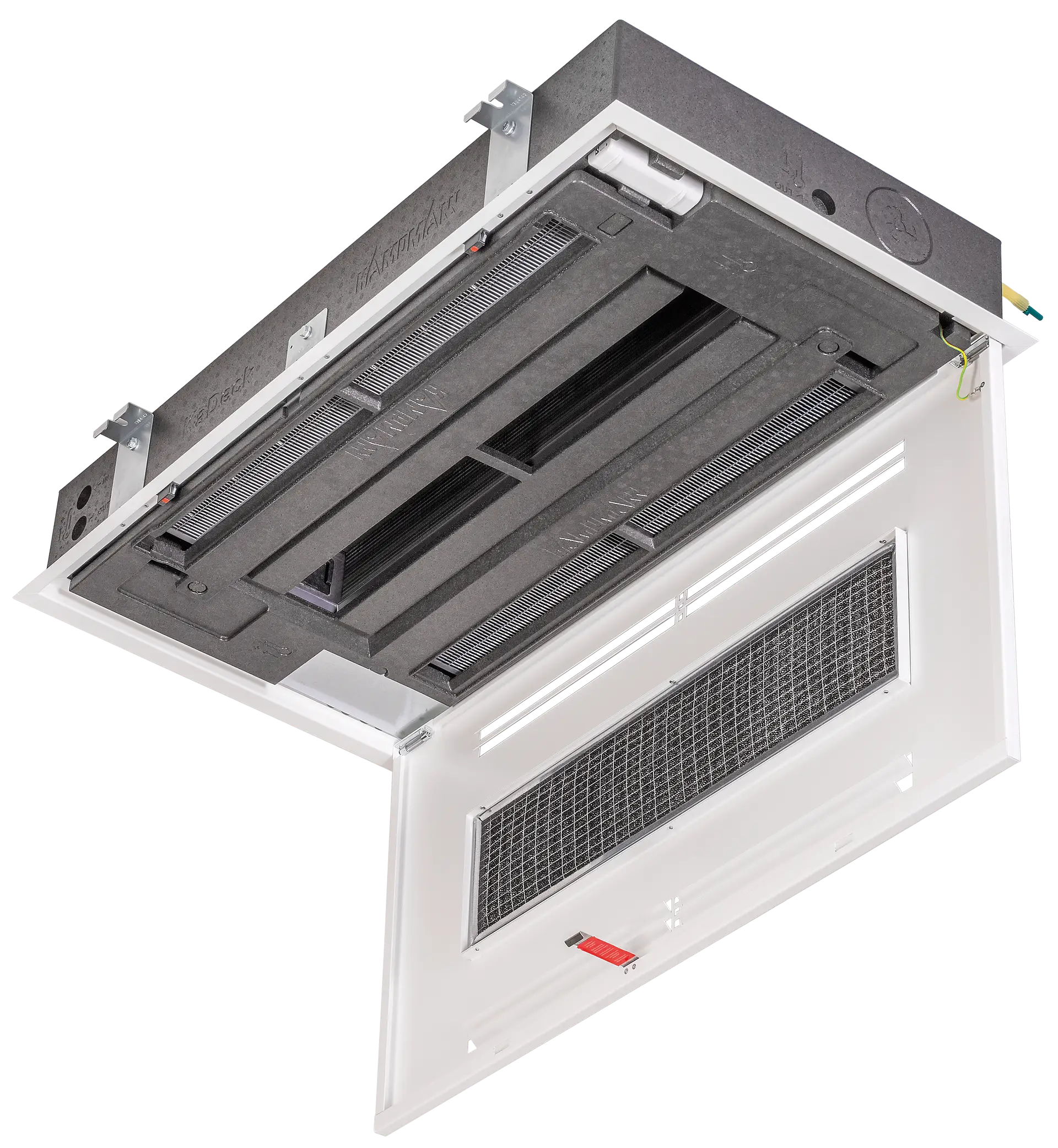
        Both versions are based on the same high-quality basic design and differ only in the equipment for condensate treatment.

        Variant for dry cooling: for operation above the dew point. It does not contain a condensate tray or pump and must not be operated with flow temperatures that cause the temperature to fall below the dew point.

        Variant for humid cooling: for operation with cooling media below the dew point. It has an integrated condensate tray and a condensate pump to reliably collect and remove any condensate.

        Unit design
        dry cooling
        wet cooling

        Ceiling grid

        Two variants enable optimum integration into different ceiling systems. For installation in suspended grid ceilings, we offer:

        • one version for grid dimension 625 × 625 mm
        • one version for grid dimension 600 × 600 mm

        The selection of the appropriate unit design depends largely on the existing ceiling system. The device drawings provide information on the number of grid fields required.

        Ceiling version
        600 x 600 mm
        625 x 625 mm

        Air outlet

        The single-sided version is particularly suitable for installation along room edges or in peripheral areas. It offers a compact solution for smaller zones or asymmetrical room layouts.

        The two-sided version is designed for central ceiling-mounted installation and has two tangential fans. This achieves a higher air output, which has a positive effect on the cooling and heat output. This variant is particularly suitable for larger rooms or uniform air distribution.

        When making the selection, particular attention should be paid to areas where people are present and the air flow in the room.

        Air outlet
        one-sided air outlet
        two-sided air outlet

        Control option

        We offer various solutions for the control and regulation of our units, which can be used depending on the application and requirements:

        Electromechanical control

        This variant is ideal for simple applications. All integrated actuators are factory-wired to terminals and can be connected to our electromechanical accessories such as thermostats or external controllers.

        KaControl MC1

        Our comprehensive comfort control offers extended control options for individual rooms or appliance groups. It can be operated either via a touch display or a web interface. Thanks to on-site 0-10 V control or common communication protocols such as Modbus RTU & TCP, BACnet and KNX, this solution is ideal for all BMS applications.

        Control option
        electromechanical 230 V
        KaControl MC1

        Installation distances and heights

        • Mounting height max. 3 m
        • Mounting height min. 2 m
        • Wall distance min. 2 m
        • Device distance min. 4 m
        • If possible, stagger the units at least 1 m apart

        Avoid the following:

        • Impairment of free air circulation due to e.g. lamps, furniture or shelves
        • Obstruction of air intake and air distribution
        • Electronic units below the unit
        • Inaccessibility for maintenance work

        Throw

        Example: KaDeck with two-sided air outlet

        at 7/12/27°C 48%rh:

        • 2 V - 0.7 m
        • 4 V - 1.8 m
        • 6 V - 2.8 m
        • 8 V - 3.8 m
        • 10 V - 4.2 m

        Coanda effect:

        • Utilization of the Coanda effect through horizontal air distribution for a high throw
        • Slow and comfortable lowering of the conditioned air into the room

        Ceiling

        • Service hatches are not necessary for both closed ceilings and system ceilings.
        • Accessibility of all maintenance-relevant components through the appliance cover.

        Mounting the units:

        • Integration into a 625 x 625 mm or 600 x 600 mm system ceiling
        • Can be installed freely suspended, suspended ceiling frame optional
        • Suspended ceiling frame available for flush ceiling connection and freely suspended
        • Further information on the suspended ceiling frame in the accessories

        condensate drain

        When operating the unit below the dew point, note the following:

        • The maximum delivery height of the condensate pump is 6 m and must not be exceeded.
        • Condensate lines must be ventilated or vented.
        • Provide lines with a permanent and continuous gradient (1%). Avoid inclines or so-called "water pockets". Use only fixed lines (no flexible hoses) for horizontal lines.
        • Connections and transitions (e.g. from hose to fixed line) must be tightly and mechanically secured, e.g. by the use of hose clamps.
        • If a siphon stop device is located at the transition point from the device to the on-site drain, it must be mounted at the highest point of the drainage profile.
        • Protect condensate-carrying lines against falling below the dew point, e.g. by means of vapour diffusion-tight insulation.

        External fresh air supply

        • Connection of centrally processed primary air to the device possible
        • permissible air temperature 14 - 15 °C
        • Primary air spigot available as an optional accessory
        • Connection diameter 80 mm
        • 1-sided devices: 60 m³/h
        • Double-sided devices: 120 m³/h (max. two nozzles, max. 60 m³/h per nozzle)

        Hygiene compliance

        • Complies with the relevant hygiene guideline VDI 6022
        • Goal: Ensuring hygienic supply air that is harmless to health
        • Applies to common rooms such as workplaces, meeting rooms, break rooms, living rooms, sports facilities and sales rooms.
        • With factory-fitted ISO Coarse filter in the intake area.
        • Accessibility of all ventilated and water-bearing components for cleaning.

        Life Cycle Assessment Data (LCA)

        • Considers the environmental impact of the product over its entire life cycle.
        • Published as an Environmental Product Declaration (EPD) in accordance with standard EN 15804.
        • Available for download at International EPD System.
        • Item number-specific life cycle assessment data in the technical data sheets.
        • Product is registered in the DGNB Navigator (building product platform).

        Serves as proof for certification systems, e.g:

        • DGNB (German Sustainable Building Council);
        • BREEAM (Building Research Establishment Environmental Assessment Method);
        • LEED (Leadership in Energy and Environmental Design).

        Results per page

          Results per page

          Page 1 of 0

          Results per page

            Results per page

            Page 1 of 0